It's been almost 3 years since I started my first work on HyperHDR, mainly dissatisfied with the performance and quality of video processing in Hyperion NG, which greatly affected also the quality and latency of ambient lighting, starting as its fork. Users who have been with me since the beginning of HyperHDR probably remember the whole background story that also contributed to this step.
Currently, judging by the significant new features introduced and their number in the last few versions, direction of their migration, the positions of both applications in role of fork have switched and Hyperion.NG can be now consider just as a fork of HyperHDR. As I develop HyperHDR with more and more help and user participation, I am not guided by any corporation or rigid framework, my ideas and improvements come from using my system almost daily and this is not limited to HyperHDR or even HDR processing itself, but also results in high-performance LED drivers such as HyperSerialESP32/HyperSerialEsp8266/HyperSPI, which made it archaic Arduino solutions offered by an old app/its sketches
Today we will briefly describe the new features in recently released HyperHDR v19, present an updated (2023) list of needed components including new interesting and cheap MS2130 USB3.0 grabber which was purchased with funds donated from my Github Sponsors. For users looking for uncompromising solutions in terms of latency, refresh rates and quality, I advise how to optimally build a new LED system using the new capabilities of HyperHDR and its LED drivers. I also haven't forgotten about the guide if you decide to go for the classic solution. Really a lot of interesting things, so let's start.
1) What's new in HyperHDR v19
2) Required hardware components
a) Device for hosting HyperHDR
b) Video components
c) Choosing LED strip
d) LED driver (updated)
e) 3.3V to 5V level shifter
f) Case for Raspberry Pi, ESP32 and power supplies
g) HyperSPI vs HyperSerialESP32/HyperSerialPico (updated)
h) How to solder the edges of LED segments
3) Challenges in designing a new sk6812/ws2812b system
4) Proposed solution: parallel multi-segment
5) Things to consider for single or multi-segment
6) Single-segment scheme for new LED system
7) Multi-segment scheme for new or upgraded LED system
8) Multi-segment HyperSerialESP32/HyperSPI firmware and HyperHDR configuration
9) Important! Optimization of HyperSerialESP32/HyperSPI settings in HyperHDR
1) What's new in HyperHDR v19
The full changelog is really long and you can find it here: link
Thanks to our user @gibahjoe who did a great job implementing Entertainment API V2, HyperHDR gained the ability to support Philips Hue gradient strip.
If you have concerns about building LED systems that require soldering, you can now use ready-made elements commonly available in stores. They are ready to use almost immediately, all you have to do is configure them first in the Philips mobile app and then in our application. Now you have an alternative to the very expensive Hue Play HDMI Sync Box and you can also use HyperHDR instead.
 You can find the tutorial here: link to the tutorial
LED designer gains new context menu. You can easily move, resize, disable or delete selected LED from your setup. Also there is 'Identify' feature which may help you to make sure you are editing corrent LED/lamp or you are just unsure it's position. Large high density LEDs configuration may make the default editor hardly readable so now you can use 'Zoom' button to switch the editor into more friendly mode. Thanks to this, you can handle even the most complex configurations, such as several lamps and Hue gradients or strips with a high density of 144 LEDs/meter.

HyperHDR finally gained a repository of Linux packages using fully Open Source solutions offered by Github (Github Pages). Nothing is hosted on external servers. You can find more details here: link
A very important 'Esp8266/ESP32 handshake' function has been added to the Adalight driver. It is used with the HyperSerialEsp8266/HyperSerialESP32 software to properly initialize the device and then read important information about the device status, software version and most importantly, statistics. If this option is enabled, the 'auto' discovery option in devices will automatically search for ESP32/Esp8266 boards first, ignoring all other potential candidates, eg a problematic Bluetooth device that we don't want to use. An auto-resume function has also been added in case of problems with late detection of the device by the system, e.g. on Webos, which may also require the use of "auto" discovery and ESP handshakes.

2) Required hardware components
No matter if you use LEDs multi-segment or classic single-segment solution, you will need these main components: USB grabber (+ HDMI splitter for MS2109/MS2130), sk6812 LED strip, SN74AHCT125N level shifter with a socket, good LED power supply (e.g. Mean Well) with appropriate power, ESP32 or ESP32-S2 device. I recommend using a wooden frame to mount the LED instead of the TV, a prototype board to mount the ESP and level shifter on it. Of course, the multi-meter is also recommended for detecting short circuits and possible cold solder joints. If you use a frame, you can direct the LEDs at a certain angle: if the frame is close to the wall (~3-5cm) it can be even 45 degrees.
A) Device for hosting HyperHDR
Unfortunately, the situation with the availability of the Raspberry Pi 4 has not improved yet, but there is hope that this will change soon: link. An increasingly important aspect when using HyperHDR is the presence of a USB3.0 port on the device. Let me just remind you that you can easily use HyperHDR even on a PC with Windows or Linux, on macOS or on various still cheap ARM-based TV boxes: I recommend especially those with Amlogic S905x3, more information can be found in my older posts on this blog. HyperHDR has very good compatibility with most of the newer builds of Armbian and Debian for various devices, especially the AARCH64 version.
B) Video components
For some time, HyperHDR has an automatic calibration of the HDR signal. This allowed for a fairly objective assessment of USB grabbers video quality using our HDR tone mapping. As you can read in this test, MS2109 presented itself best. However, this required modifications to the brightness, contrast and saturation, which the manufacturer set well beyond the neutral settings. Which could be a problem e.g. if you are using HyperHDR on macOS as it is not possible to set them on this system.
Just before publishing this post, I received an improved version of this grabber: MS2130. It is a true USB3.0 cheap video grabber with factory neutral processing settings and no adjustments required. Still only HyperHDR allows you to use its capabilities optimally in terms of quality for SDR and HDR processing (yes, SDR is also affected because of YUV full range and FCC coefs). The results are sensational, although the grabber itself requires further testing and a full review will be published later. I recommend following this topic for more details: MS2130 link
No matter if you choose the proven MS2109 grabber or decide to experiment with the latest MS2130, you still need an HDMI splitter. I have two of them for a long time: FeinTech VSP01201 and Ezcoo EZ-SP12H2. Both work well, although there are some differences between them and as some users reported, the firmware update in the case of EZ-SP12H2 can be troublesome or even dangerous. Nevertheless, the manufacturer's efforts to support the product should be appreciated. This model of Ezcoo splitter does not support CEC, but has another unique feature for Dolby Vision (LLDV) that can be activated: link
C) Choosing LED strip
Currently, the best quality for our purposes is offered by the sk6812 RGBW cold white. If you are worried that the "Cold White" version of the SK6812 RGBW is bluish, this is completely false. You may experience such effect from RGB LED strips like ws2812b or APA102, but not from this RGBW LEDs version. We do not use LED strips for room lighting where warm color characteristic is preferred, but for precise Ambient Lighting. I know a lot of users choose the "Neutral White" version, but you also need to know that the our LED drivers do a lot of things underneath to try to fix the "Neutral White" unbalanced color profile and it is definitely not a good or "neutral" thing. I've both SK6812 version and can compare them side by side. Still whichever version you choose, the quality will be much better than with RGB LED strips such as ws2812b or clones of APA102.
You should read these market ads as:
D) LED driver
The recommended LED driver is ESP32 or ESP32-S2 Lolin mini device. Unless new models are released, the Arduino as an LED driver is a thing of the past, and the Esp8266 is slowly following the same path. Below are examples of boards that I work with on a daily basis and have the best support from my side: ESP32 MH-ET Live (CH9102x) and ESP32-S2 Lolin mini. This does not mean, however, that we limit ourselves to them: almost every board with similar parameters will be supported. The exception is bad designed or manufactured boards like the model reported by our users: link and link. Such "optimization" of costs can happen even between successive revisions of the same model. Always check product reviews before buying from a particular retailer.


Since the cost of transport is quite a large part of the total and takes a long time, I always order at least 2 ESP boards from Aliexpress, which gives me a spare in case one of them fails: damage in transit, bad flash memory or damage during soldering of pins can always happen. It's not a big deal as they usually cost around $2 to $4 only.
Update: support for Raspberry Pi Pico (Rp2040) boards has been added using my new project HyperSerialPico More details can be found here: link. You can use it as a solid and cheap alternative to HyperSerialESP32 solution. Some of rp2040 boards (e.g. selected Adafruit and Pimoroni boards) have already built-in 3.3V to 5V level shifter, which greatly simplifies the whole setup when HyperSerialPico is used!


E) 3.3V to 5V level shifter
As it has been explained many times, the logic of the ESP32/ESP8266/ESP32-S2/Raspberry Pi uses a voltage of up to 3.3V, while the driver in the LEDs works with a voltage of up to 5V. If we don't use 3.3V to 5V level shifter our solution will be out of technical specification and you can expect all sorts of problems: from LEDs not working at all, to occasional flashes or a complete "disco" effect. Similar symptoms can occur if you do not provide "common ground" between the driver/level-shifter and the LEDs. We recommend using a multi-channel level shifter: SN74AHCT125N/74AHCT125 with a socket which allows you to replace the chip if needed. You can find more here: link
Example: you can use the cut off legs of the resistors (thin wires) to make the paths on the PCB easier. Because I had a 2x8 IC socket and the level shifter is only 2x7, the first column of the socket is empty. For this particular board and ESP32-S2 mini, the LED output is on GPIO16 and GPIO33. The yellow pinout is optional and it's used for HyperSPI connection: if you don't use, you don't need to solder it.
F) Case for Raspberry Pi, ESP32 and power supplies
If you use a modular power supply, you must take special precautions and ensure that all high-voltage cables are securely fastened and insulated. The whole thing should be enclosed in a case while ensuring at least passive ventilation (ventilation holes). Never open it when the power cord is connected. I'm absolutely not encouraging anyone to follow this scheme as there is potential hazard related to the high voltage from the modular power supply. You can use a sealed laptop 5v power supply as an alternative. I never leave the system without attention and power it off with Power Cube Remote when not used. The Rpi with Raspberry Pi OS is using the read-only system on SD card so it can withstand sudden powering off (read more here)
In my project I used a Kradex Z17W case, screw-in copper sockets to attach the ESP32 and Raspberry Pi, screws to attach Mean-Well LRS-150F-5 power supply, IEC 320 3-pin 10A 250V sockets C14 input male plug with 1A fuse and a molex for the LED strip output (for higher currents you will need, for example, an XT60 connector or its equivalent). Raspberry Pi is using dedicated 2A USB power supply, not Mean-Well.

G) HyperSPI vs HyperSerialESP32
HyperSPI is by far the optimal solution: the SPI protocol is hardware accelerated and is much faster, so consumes much less system resources and provides lower latency than HyperSerialESP32., which involves the use of USB serial port drivers to communicate (but works over long distance even few meters). Contrary to appearances, it is also very easy to build because it requires the use of only 3-4 short 15-20cm dupont wires to connect the SPI interfaces and the grounds.
But HyperSPI can only be used if the device offers an SPI interface and is supported by the operating system. In practice, this limits its use to the Raspberry Pi (and OrangePi as reported by users). An additional limitation for HyperSPI is the distance: it can only be used on very short distances of 15-20 cm from Raspberry Pi. Of course, if you have a supported device and the distance between it and the ESP will be short, you can use it as you want with either HyperSPI or HyperSerialESP32.
Update: support for Raspberry Pi Pico (Rp2040) boards has been recently added using my new project HyperSerialPico More details can be found here: link You can consider it as an alternative to HyperSerialESP32 solution. Also Pico thanks to the PIO I/O coprocessor is able to produce a very high quality and precise signal, which is especially required for the Neopixel sk6812/ws8212b LED strips. Some of rp2040 boards (e.g. selected Adafruit and Pimoroni boards) have already built-in 3.3V to 5V level shifter, which greatly simplifies the whole setup when HyperSerialPico is used!
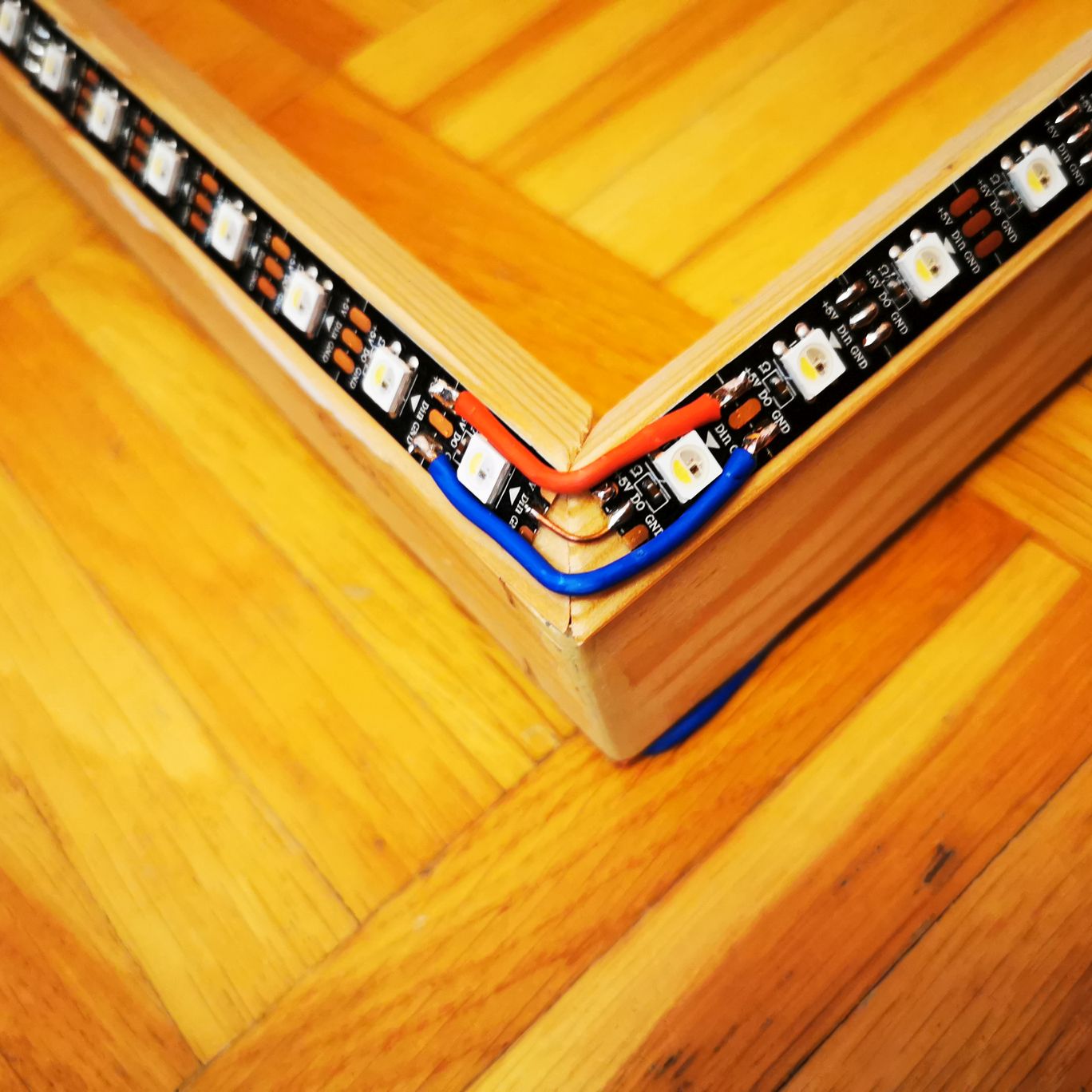
H) How to solder the edges of LED segments
The cable for +5V and the ground should be thicker, e.g. typically 0.75-1.5mm2 (depending on the predictable load), the signal cable can be very thin. Everyone can use their technique here, one that suits them. Start by applying tin to soldering points on LED strip. Using flux really makes soldering much easier.
 For the data line I use thin copper solid wire aprox. 4-5cm length. I start by soldering one end of the wire to the first LED segment, I bend it and remove excess insulation and soldered it to the second LED segment. Then I cut the excess part of the wire with my wire cutting plier.Be careful because the wire can heat up to high temperatures when soldering so use some insulation and do not hold it with your bare fingers.Then I solder the cables connecting +5V and the grounds of LED segments as in the attached photo.
 As you can see I also use 45° wooden strip (e.g. from the Obi store) attached to the wooden frame.
3) Challenges in designing a new sk6812/ws2812b system
Unfortunately, a certain disadvantage of Neopixel type LEDs like sk6812 is a rather slow data bus ~800kHz. This is especially true for RGBW LEDs because we need to send as much as 4 bytes of data for each LED and only 3 bytes in case of RGB ws2812b. This limits the maximum refresh rate and causes latency. However, the latest versions of HyperSerialESP32 and HyperSPI offer HyperHDR a solution to this problem without compromising quality.
Since we can't increase the speed of the data bus, we have to work around this problem in a different way: split a long single LED strip into two smaller ones. In this way, each of them will have a separate data bus and will be able to be refreshed at twice as often as the original single and long LED strip. So far, the problem remained how to easily offer the configuration of such a solution and ensure perfect synchronization between both smaller segments? After all, we don't want both segments to render even slightly out of sync scenes or make the construction or configuration of such a system so complicated, that it will surpass the abilities of an average mortal.
4) Proposed solution: parallel multi-segment
This is where the latest HyperSerialESP32 v9 and HyperSPI v9 come to the rescue with the true parallel multi-segment output. Just choose the solution that suits you better. Parallel multi-segment mode is currently supported only by ESP32 and ESP32-S2 (mini lolin). Unfortunately, today the Esp8266 is too limited to offer similar solution. Parallel multi-segment output means that the signal for both segments is sent at exactly the same time using ESP parallel I2S interface, so both segments are perfectly synchronized.
Parallel multi-segment not to be confused with WLED segments: it's a completely different solution that can't provide the same experience at all in terms of quality (DMA pre-fill mode to ensure smooth rendering) and synchronization of segments.
5) Things to consider for single or multi-segment
Is it worth building or upgrading your system to parallel multi-segment mode? You have to answer this question yourself, taking into account the parameters of your setup. It complicates a bit building and configuration of new setup compared to the single LED segment, but this is certainly the most optimal way to use sk6812 or ws2812b with HyperHDR. The benefits depend on whether you are using RGB or RGBW and how many LEDs you intend to use and start from 300 RGBW LEDs, for RGB this number is higher. Example results of maximum refresh rate:
And if you dont use parallel multi-segment setup:
And few words about Neopixel data line latency.
Let's calculate how long it takes to send LED color information over the Neopixel data line (800kHz).
Single segment, sk6812 RGBW LEDs:
Multi-segment, sk6812 RGBW LEDs divided into two smaller segments:
6) Single-segment scheme for new LED system
Many thanks for @pavel-ponomarev for help with the diagrams. Connections between Rpi pinout and ESP pinout are needed only if you use HyperSPI. For HyperSerialESP32 only full USB connection between ESP and Rpi is neccesery.

The above Fritzing sketch is available here for download.
You only need the already built firmware from the HyperSPI/HyperSerialESP32 Releases section. Upload it to the ESP device and configure it according to the instructions you will find on the project homepages. For general HyperHDR setup instructions, see the HyperHDR wiki. Then skip to "Optimizing HyperSerialESP32/HyperSPI chapter".
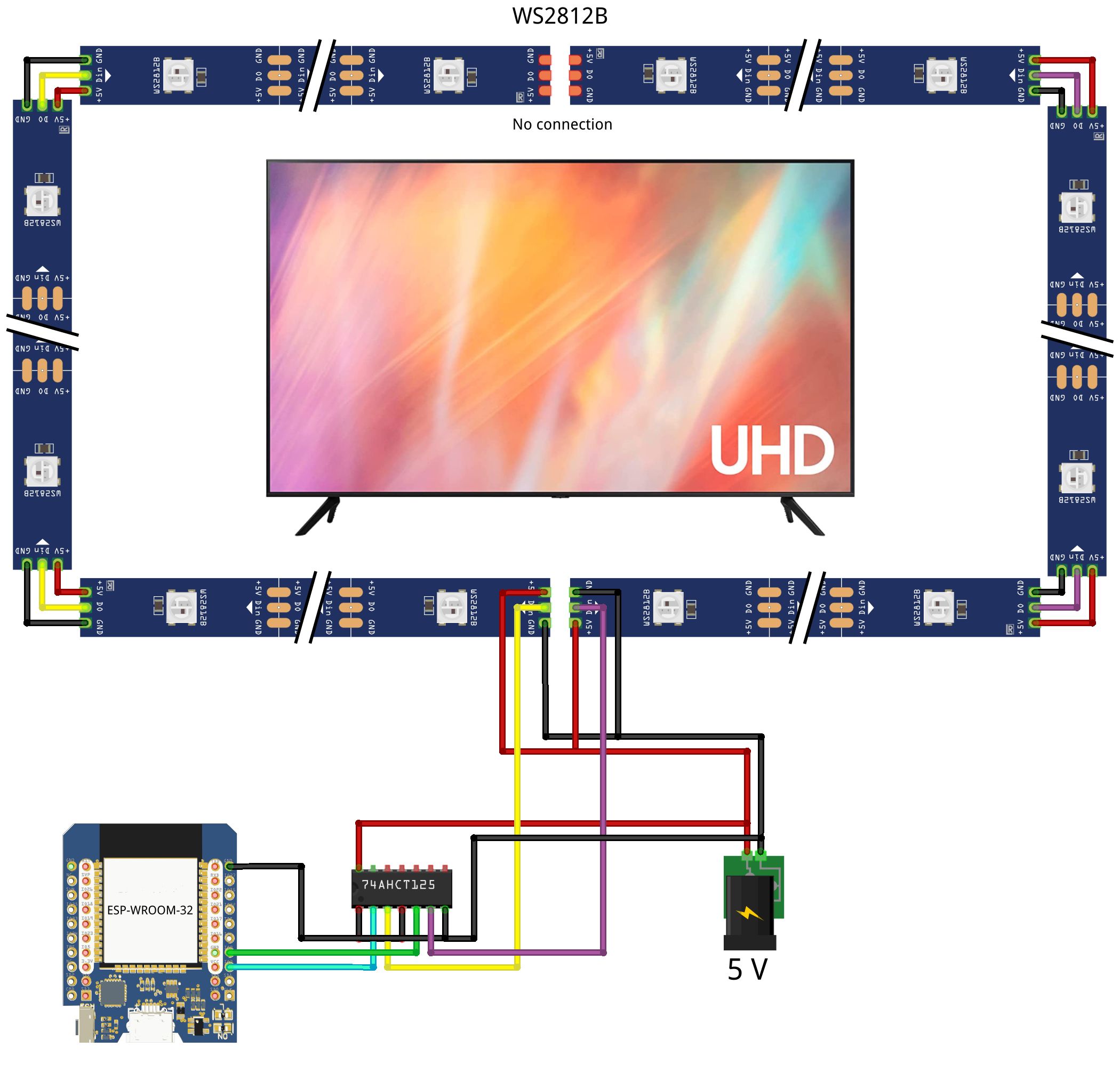
7) Multi-segment scheme for new or upgraded LED system
Upgrading your current setup to parallel multi-segment: depending on how it's built, you'll need to carefully physically separate the data lines in the middle of the LED strip to get two equal smaller segments. You don't need to break the existing +5V and ground lines, although it may give you more room to firmly attach the new data line. Connect a new data line cable at the beginning of the segment that no longer has a data input. After soldering, secure it mechanically permanently using e.g. hot glue. Make sure it is not touching/shorting adjacent ground or +5V lines. You don't use the SECOND_SEGMENT_REVERSED option described later when compiling your firmware for ESP driver. Remember that both data lines from the ESP/level-shifter to the LED strip should be fairly even and short.

The above Fritzing sketch is available here for download.
The construction of the new system is much simpler: from the LED strips you build two segments facing in opposite directions. The data lines cannot connect between them. One picture will replace many words (thank you @pavel-ponomarev).

8) Multi-segment HyperSerialESP32/HyperSPI firmware and HyperHDR configuration
For multi-segment we need to compile our own HyperSerialESP32/hyperSPI firmware to take into account where the second segment starts and whether it is reversed (new setup) or not (upgrade of the old single to multi-segment). But don't worry: you don't need to install any application on your computer or have any programming skills to do it. The whole process takes only a few minutes and is completely online. All you need is a free Github account.
Follow the manual available here or here and stop at step 5.
For HyperSerialESP32 now we can increase in platformio.ini configuration file the default serial port speed: for ESP32 MH-ET Live (CH9102x) set

There are 3 options when defining the second segment (append
We find in the edited file sections suitable for our ESP (ESP32 and ESP32-S2 have separate sections) and the type of LEDs and define the second segment there.
For example, I have an SK6812 RGBW Cold White segment of 340 LEDs split into two 170 segments in opposite directions (new setup). I'm using ESP32 and HyperSerialESP32 and the LED output for the second segment is GPIO4.My setup would look like this: locate

Another example, I have an WS2812B RGB segment of 500 LEDs split into two 250 segments in same direction (upgraded setup). I'm using ESP32-S2 mini and HyperSerialESP32 and the LED output for the second segment is GPIO4. My setup would look like this: locate

Now you can commit changes to platformio.ini with the button at the bottom and wait a moment for Github Action to compile them, which is described in the next steps on the wiki. Download from Github Action the zip firmware package, unpack it and find the version you configured. Then follow the instructions on HyperSerialESP32 and HyperSPI to flash this firmware.
Multi-segment in HyperHDR should be configured as one continuous segment. Everything is done in the HyperSerialESP32/HyperSPI software transparently and does not affect the configuration of the LED strip in HyperHDR which treats it in the same way as a single-segment. For example, if you have a multi-segment divided into two 250 LEDs segments you should configure it in HyperHDR as standard single LED strip of 500 LEDs. Check the HyperHDR wiki for more details.
9) Important! Optimization of HyperSerialESP32/HyperSPI settings in HyperHDR
We cannot force the Neopixel sk6812/ws2812b LED strip to render more frames than its internal data line can handle. Therefore, to avoid dropped frames or their buffering, which can sometimes introduce a slight lag, you should set the maximum refresh in smoothing so that the LED strip is able to render.
To do so, follow the instructions at HyperSerialESP32 or at HyperSPI. Remember that you need to set color as an effect, not an animation like "Rainbow swirl" because they have predefined settings that you cannot change. For HyperSerialESP32 you also need to have an 'Esp8266/ESP32 handshake' option enabled in HyperHDR Adalight driver.
I will show on the example of HyperSerialESP32 how to do it. I have defined a single segment of 400 RGBW LEDs in HyperHDR. I enabled the 'Continues output' option in Smoothing configuration and run the color as an active effect according to the manual mentioned earlier. From the benchmarks in the table that can be found in this section, I know that the expected maximum refresh rate is between 83Hz and 42Hz. So I set it now to the highest value for testing: 83Hz.

After a few seconds, I stop the LED device in the Remote section and find the actual refresh rate in the logs. The test should be carried out several times (enable and disable the LED strip again) to eliminate possible interference.

So I know that my LEDs can be refreshed with a maximum of 62Hz. If the value is greater than 100 for smaller configurations, it usually doesn't make sense to set it so high. I go back to the Smoothing settings and set the refresh according to the result. Then I disable the 'Continues output' option. That's it. The same procedure applies to a multi-segment setup, although of course you can expect a higher refresh rate.
 It's been almost 3 years since I started my first work on HyperHDR, mainly dissatisfied with the performance and quality of video processing in Hyperion NG, which greatly affected also the quality and latency of ambient lighting, starting as its fork. Users who have been with me since the beginning of HyperHDR probably remember the whole background story that also contributed to this step.
Currently, judging by the significant new features introduced and their number in the last few versions, direction of their migration, the positions of both applications in role of fork have switched and Hyperion.NG can be now consider just as a fork of HyperHDR. As I develop HyperHDR with more and more help and user participation, I am not guided by any corporation or rigid framework, my ideas and improvements come from using my system almost daily and this is not limited to HyperHDR or even HDR processing itself, but also results in high-performance LED drivers such as HyperSerialESP32/HyperSerialEsp8266/HyperSPI, which made it archaic Arduino solutions offered by an old app/its sketches
Today we will briefly describe the new features in recently released HyperHDR v19, present an updated (2023) list of needed components including new interesting and cheap MS2130 USB3.0 grabber which was purchased with funds donated from my Github Sponsors. For users looking for uncompromising solutions in terms of latency, refresh rates and quality, I advise how to optimally build a new LED system using the new capabilities of HyperHDR and its LED drivers. I also haven't forgotten about the guide if you decide to go for the classic solution. Really a lot of interesting things, so let's start.
1) What's new in HyperHDR v19
2) Required hardware components
a) Device for hosting HyperHDR
b) Video components
c) Choosing LED strip
d) LED driver (updated)
e) 3.3V to 5V level shifter
f) Case for Raspberry Pi, ESP32 and power supplies
g) HyperSPI vs HyperSerialESP32/HyperSerialPico (updated)
h) How to solder the edges of LED segments
3) Challenges in designing a new sk6812/ws2812b system
4) Proposed solution: parallel multi-segment
5) Things to consider for single or multi-segment
6) Single-segment scheme for new LED system
7) Multi-segment scheme for new or upgraded LED system
8) Multi-segment HyperSerialESP32/HyperSPI firmware and HyperHDR configuration
9) Important! Optimization of HyperSerialESP32/HyperSPI settings in HyperHDR
1) What's new in HyperHDR v19
The full changelog is really long and you can find it here: link
Thanks to our user @gibahjoe who did a great job implementing Entertainment API V2, HyperHDR gained the ability to support Philips Hue gradient strip.
| Before | After |
|---|---|
 | 
|
If you have concerns about building LED systems that require soldering, you can now use ready-made elements commonly available in stores. They are ready to use almost immediately, all you have to do is configure them first in the Philips mobile app and then in our application. Now you have an alternative to the very expensive Hue Play HDMI Sync Box and you can also use HyperHDR instead.

LED designer gains new context menu. You can easily move, resize, disable or delete selected LED from your setup. Also there is 'Identify' feature which may help you to make sure you are editing corrent LED/lamp or you are just unsure it's position. Large high density LEDs configuration may make the default editor hardly readable so now you can use 'Zoom' button to switch the editor into more friendly mode. Thanks to this, you can handle even the most complex configurations, such as several lamps and Hue gradients or strips with a high density of 144 LEDs/meter.

HyperHDR finally gained a repository of Linux packages using fully Open Source solutions offered by Github (Github Pages). Nothing is hosted on external servers. You can find more details here: link
A very important 'Esp8266/ESP32 handshake' function has been added to the Adalight driver. It is used with the HyperSerialEsp8266/HyperSerialESP32 software to properly initialize the device and then read important information about the device status, software version and most importantly, statistics. If this option is enabled, the 'auto' discovery option in devices will automatically search for ESP32/Esp8266 boards first, ignoring all other potential candidates, eg a problematic Bluetooth device that we don't want to use. An auto-resume function has also been added in case of problems with late detection of the device by the system, e.g. on Webos, which may also require the use of "auto" discovery and ESP handshakes.

2) Required hardware components
No matter if you use LEDs multi-segment or classic single-segment solution, you will need these main components: USB grabber (+ HDMI splitter for MS2109/MS2130), sk6812 LED strip, SN74AHCT125N level shifter with a socket, good LED power supply (e.g. Mean Well) with appropriate power, ESP32 or ESP32-S2 device. I recommend using a wooden frame to mount the LED instead of the TV, a prototype board to mount the ESP and level shifter on it. Of course, the multi-meter is also recommended for detecting short circuits and possible cold solder joints. If you use a frame, you can direct the LEDs at a certain angle: if the frame is close to the wall (~3-5cm) it can be even 45 degrees.
A) Device for hosting HyperHDR
Unfortunately, the situation with the availability of the Raspberry Pi 4 has not improved yet, but there is hope that this will change soon: link. An increasingly important aspect when using HyperHDR is the presence of a USB3.0 port on the device. Let me just remind you that you can easily use HyperHDR even on a PC with Windows or Linux, on macOS or on various still cheap ARM-based TV boxes: I recommend especially those with Amlogic S905x3, more information can be found in my older posts on this blog. HyperHDR has very good compatibility with most of the newer builds of Armbian and Debian for various devices, especially the AARCH64 version.
B) Video components
For some time, HyperHDR has an automatic calibration of the HDR signal. This allowed for a fairly objective assessment of USB grabbers video quality using our HDR tone mapping. As you can read in this test, MS2109 presented itself best. However, this required modifications to the brightness, contrast and saturation, which the manufacturer set well beyond the neutral settings. Which could be a problem e.g. if you are using HyperHDR on macOS as it is not possible to set them on this system.
Just before publishing this post, I received an improved version of this grabber: MS2130. It is a true USB3.0 cheap video grabber with factory neutral processing settings and no adjustments required. Still only HyperHDR allows you to use its capabilities optimally in terms of quality for SDR and HDR processing (yes, SDR is also affected because of YUV full range and FCC coefs). The results are sensational, although the grabber itself requires further testing and a full review will be published later. I recommend following this topic for more details: MS2130 link
No matter if you choose the proven MS2109 grabber or decide to experiment with the latest MS2130, you still need an HDMI splitter. I have two of them for a long time: FeinTech VSP01201 and Ezcoo EZ-SP12H2. Both work well, although there are some differences between them and as some users reported, the firmware update in the case of EZ-SP12H2 can be troublesome or even dangerous. Nevertheless, the manufacturer's efforts to support the product should be appreciated. This model of Ezcoo splitter does not support CEC, but has another unique feature for Dolby Vision (LLDV) that can be activated: link
On the picture from left: MS2109, MS2130, FeinTech VSP01201 and Ezcoo EZ-SP12H2.

C) Choosing LED strip
Currently, the best quality for our purposes is offered by the sk6812 RGBW cold white. If you are worried that the "Cold White" version of the SK6812 RGBW is bluish, this is completely false. You may experience such effect from RGB LED strips like ws2812b or APA102, but not from this RGBW LEDs version. We do not use LED strips for room lighting where warm color characteristic is preferred, but for precise Ambient Lighting. I know a lot of users choose the "Neutral White" version, but you also need to know that the our LED drivers do a lot of things underneath to try to fix the "Neutral White" unbalanced color profile and it is definitely not a good or "neutral" thing. I've both SK6812 version and can compare them side by side. Still whichever version you choose, the quality will be much better than with RGB LED strips such as ws2812b or clones of APA102.
You should read these market ads as:
- SK6812 Warm White → "Orange" (avoid!)
- SK6812 Neutral White → "Warm"
- SK6812 Cold White → "Neutral" (preffered)
D) LED driver
The recommended LED driver is ESP32 or ESP32-S2 Lolin mini device. Unless new models are released, the Arduino as an LED driver is a thing of the past, and the Esp8266 is slowly following the same path. Below are examples of boards that I work with on a daily basis and have the best support from my side: ESP32 MH-ET Live (CH9102x) and ESP32-S2 Lolin mini. This does not mean, however, that we limit ourselves to them: almost every board with similar parameters will be supported. The exception is bad designed or manufactured boards like the model reported by our users: link and link. Such "optimization" of costs can happen even between successive revisions of the same model. Always check product reviews before buying from a particular retailer.


Since the cost of transport is quite a large part of the total and takes a long time, I always order at least 2 ESP boards from Aliexpress, which gives me a spare in case one of them fails: damage in transit, bad flash memory or damage during soldering of pins can always happen. It's not a big deal as they usually cost around $2 to $4 only.
Update: support for Raspberry Pi Pico (Rp2040) boards has been added using my new project HyperSerialPico More details can be found here: link. You can use it as a solid and cheap alternative to HyperSerialESP32 solution. Some of rp2040 boards (e.g. selected Adafruit and Pimoroni boards) have already built-in 3.3V to 5V level shifter, which greatly simplifies the whole setup when HyperSerialPico is used!


E) 3.3V to 5V level shifter
As it has been explained many times, the logic of the ESP32/ESP8266/ESP32-S2/Raspberry Pi uses a voltage of up to 3.3V, while the driver in the LEDs works with a voltage of up to 5V. If we don't use 3.3V to 5V level shifter our solution will be out of technical specification and you can expect all sorts of problems: from LEDs not working at all, to occasional flashes or a complete "disco" effect. Similar symptoms can occur if you do not provide "common ground" between the driver/level-shifter and the LEDs. We recommend using a multi-channel level shifter: SN74AHCT125N/74AHCT125 with a socket which allows you to replace the chip if needed. You can find more here: link
Example: you can use the cut off legs of the resistors (thin wires) to make the paths on the PCB easier. Because I had a 2x8 IC socket and the level shifter is only 2x7, the first column of the socket is empty. For this particular board and ESP32-S2 mini, the LED output is on GPIO16 and GPIO33. The yellow pinout is optional and it's used for HyperSPI connection: if you don't use, you don't need to solder it.
 |
 |
 |
|
F) Case for Raspberry Pi, ESP32 and power supplies
If you use a modular power supply, you must take special precautions and ensure that all high-voltage cables are securely fastened and insulated. The whole thing should be enclosed in a case while ensuring at least passive ventilation (ventilation holes). Never open it when the power cord is connected. I'm absolutely not encouraging anyone to follow this scheme as there is potential hazard related to the high voltage from the modular power supply. You can use a sealed laptop 5v power supply as an alternative. I never leave the system without attention and power it off with Power Cube Remote when not used. The Rpi with Raspberry Pi OS is using the read-only system on SD card so it can withstand sudden powering off (read more here)
In my project I used a Kradex Z17W case, screw-in copper sockets to attach the ESP32 and Raspberry Pi, screws to attach Mean-Well LRS-150F-5 power supply, IEC 320 3-pin 10A 250V sockets C14 input male plug with 1A fuse and a molex for the LED strip output (for higher currents you will need, for example, an XT60 connector or its equivalent). Raspberry Pi is using dedicated 2A USB power supply, not Mean-Well.

|

|

|

|

G) HyperSPI vs HyperSerialESP32
HyperSPI is by far the optimal solution: the SPI protocol is hardware accelerated and is much faster, so consumes much less system resources and provides lower latency than HyperSerialESP32., which involves the use of USB serial port drivers to communicate (but works over long distance even few meters). Contrary to appearances, it is also very easy to build because it requires the use of only 3-4 short 15-20cm dupont wires to connect the SPI interfaces and the grounds.
But HyperSPI can only be used if the device offers an SPI interface and is supported by the operating system. In practice, this limits its use to the Raspberry Pi (and OrangePi as reported by users). An additional limitation for HyperSPI is the distance: it can only be used on very short distances of 15-20 cm from Raspberry Pi. Of course, if you have a supported device and the distance between it and the ESP will be short, you can use it as you want with either HyperSPI or HyperSerialESP32.
Update: support for Raspberry Pi Pico (Rp2040) boards has been recently added using my new project HyperSerialPico More details can be found here: link You can consider it as an alternative to HyperSerialESP32 solution. Also Pico thanks to the PIO I/O coprocessor is able to produce a very high quality and precise signal, which is especially required for the Neopixel sk6812/ws8212b LED strips. Some of rp2040 boards (e.g. selected Adafruit and Pimoroni boards) have already built-in 3.3V to 5V level shifter, which greatly simplifies the whole setup when HyperSerialPico is used!
H) How to solder the edges of LED segments
The cable for +5V and the ground should be thicker, e.g. typically 0.75-1.5mm2 (depending on the predictable load), the signal cable can be very thin. Everyone can use their technique here, one that suits them. Start by applying tin to soldering points on LED strip. Using flux really makes soldering much easier.

 |
 |
3) Challenges in designing a new sk6812/ws2812b system
Unfortunately, a certain disadvantage of Neopixel type LEDs like sk6812 is a rather slow data bus ~800kHz. This is especially true for RGBW LEDs because we need to send as much as 4 bytes of data for each LED and only 3 bytes in case of RGB ws2812b. This limits the maximum refresh rate and causes latency. However, the latest versions of HyperSerialESP32 and HyperSPI offer HyperHDR a solution to this problem without compromising quality.
Since we can't increase the speed of the data bus, we have to work around this problem in a different way: split a long single LED strip into two smaller ones. In this way, each of them will have a separate data bus and will be able to be refreshed at twice as often as the original single and long LED strip. So far, the problem remained how to easily offer the configuration of such a solution and ensure perfect synchronization between both smaller segments? After all, we don't want both segments to render even slightly out of sync scenes or make the construction or configuration of such a system so complicated, that it will surpass the abilities of an average mortal.
4) Proposed solution: parallel multi-segment
This is where the latest HyperSerialESP32 v9 and HyperSPI v9 come to the rescue with the true parallel multi-segment output. Just choose the solution that suits you better. Parallel multi-segment mode is currently supported only by ESP32 and ESP32-S2 (mini lolin). Unfortunately, today the Esp8266 is too limited to offer similar solution. Parallel multi-segment output means that the signal for both segments is sent at exactly the same time using ESP parallel I2S interface, so both segments are perfectly synchronized.
Parallel multi-segment not to be confused with WLED segments: it's a completely different solution that can't provide the same experience at all in terms of quality (DMA pre-fill mode to ensure smooth rendering) and synchronization of segments.
5) Things to consider for single or multi-segment
Is it worth building or upgrading your system to parallel multi-segment mode? You have to answer this question yourself, taking into account the parameters of your setup. It complicates a bit building and configuration of new setup compared to the single LED segment, but this is certainly the most optimal way to use sk6812 or ws2812b with HyperHDR. The benefits depend on whether you are using RGB or RGBW and how many LEDs you intend to use and start from 300 RGBW LEDs, for RGB this number is higher. Example results of maximum refresh rate:
| Parallel multi-segment mode / Device | ESP32 MH-ET LIVE mini @4Mb speed |
ESP32-S2 Lolin mini @5Mb speed |
|---|---|---|
| 300LEDs RGBW Refresh rate/continues output=100Hz SECOND_SEGMENT_START_INDEX=150 |
100Hz | 100Hz |
| 600LEDs RGBW Refresh rate/continues output=83Hz SECOND_SEGMENT_START_INDEX=300 |
83Hz | 83Hz |
| 900LEDs RGBW Refresh rate/continues output=55Hz SECOND_SEGMENT_START_INDEX=450 |
55Hz | 55Hz |
And if you dont use parallel multi-segment setup:
| Single RGBW LED strip / Device | ESP32/ESP32-S2 HyperSerialESP32 v9 |
|---|---|
| 300LEDs RGBW Refresh rate/continues output=83Hz | 83Hz |
| 600LEDs RGBW Refresh rate/continues output=42Hz | 42Hz |
| 900LEDs RGBW Refresh rate/continues output=28Hz | 28Hz |
And few words about Neopixel data line latency.
Let's calculate how long it takes to send LED color information over the Neopixel data line (800kHz).
Single segment, sk6812 RGBW LEDs:
300 RGBW ⇒ 300 * 4 bytes ⇒ 300 * 4 * 8 bits ⇒ 9600 bits ⇒ 9600 / 800000 ⇒ 12 ms
600 RGBW ⇒ 24 ms
900 RGBW ⇒ 36 ms
Multi-segment, sk6812 RGBW LEDs divided into two smaller segments:
300 (2x150) RGBW ⇒ 150 * 4 bytes ⇒ 150 * 4 * 8 bits ⇒ 4800 bits ⇒ 4800 / 800000 ⇒ 6 ms
600 (2x300) RGBW ⇒ 12 ms
900 (2x450) RGBW ⇒ 18 ms
6) Single-segment scheme for new LED system
Many thanks for @pavel-ponomarev for help with the diagrams. Connections between Rpi pinout and ESP pinout are needed only if you use HyperSPI. For HyperSerialESP32 only full USB connection between ESP and Rpi is neccesery.

The above Fritzing sketch is available here for download.
You only need the already built firmware from the HyperSPI/HyperSerialESP32 Releases section. Upload it to the ESP device and configure it according to the instructions you will find on the project homepages. For general HyperHDR setup instructions, see the HyperHDR wiki. Then skip to "Optimizing HyperSerialESP32/HyperSPI chapter".
7) Multi-segment scheme for new or upgraded LED system
Upgrading your current setup to parallel multi-segment: depending on how it's built, you'll need to carefully physically separate the data lines in the middle of the LED strip to get two equal smaller segments. You don't need to break the existing +5V and ground lines, although it may give you more room to firmly attach the new data line. Connect a new data line cable at the beginning of the segment that no longer has a data input. After soldering, secure it mechanically permanently using e.g. hot glue. Make sure it is not touching/shorting adjacent ground or +5V lines. You don't use the SECOND_SEGMENT_REVERSED option described later when compiling your firmware for ESP driver. Remember that both data lines from the ESP/level-shifter to the LED strip should be fairly even and short.

The above Fritzing sketch is available here for download.
The construction of the new system is much simpler: from the LED strips you build two segments facing in opposite directions. The data lines cannot connect between them. One picture will replace many words (thank you @pavel-ponomarev).
8) Multi-segment HyperSerialESP32/HyperSPI firmware and HyperHDR configuration
For multi-segment we need to compile our own HyperSerialESP32/hyperSPI firmware to take into account where the second segment starts and whether it is reversed (new setup) or not (upgrade of the old single to multi-segment). But don't worry: you don't need to install any application on your computer or have any programming skills to do it. The whole process takes only a few minutes and is completely online. All you need is a free Github account.
Follow the manual available here or here and stop at step 5.
For HyperSerialESP32 now we can increase in platformio.ini configuration file the default serial port speed: for ESP32 MH-ET Live (CH9102x) set
4000000 and for ESP32-S2 Lolin mini set 5000000 . Remember than you need to use this new speed also in the HyperHDR Adalight driver instead of the default 2000000 speed. You don't need to change the serial port speed for HyperSPI.There are 3 options when defining the second segment (append
-D prefix) in HyperSerialESP32 and HyperSPI :SECOND_SEGMENT_START_INDEXstart of the second segment, total number of LEDs in the first segmentSECOND_SEGMENT_DATA_PINthis is the GPIO data pin for your second stripe. Recommend to use GPIO4.SECOND_SEGMENT_REVERSEDif present, the second segment is reversed relative to the first one (new setup). We do not use this option if both segments have the same direction (upgrade of the old single-segment setup)
We find in the edited file sections suitable for our ESP (ESP32 and ESP32-S2 have separate sections) and the type of LEDs and define the second segment there.
For example, I have an SK6812 RGBW Cold White segment of 340 LEDs split into two 170 segments in opposite directions (new setup). I'm using ESP32 and HyperSerialESP32 and the LED output for the second segment is GPIO4.My setup would look like this: locate
[env:SK6812_RGBW_COLD] section for ESP32 and SK6812 RGBW Cold white. Append to build_flags my configuration:build_flags = ... ${env.build_flags} -DSECOND_SEGMENT_START_INDEX=170 -DSECOND_SEGMENT_DATA_PIN=4 -DSECOND_SEGMENT_REVERSEDAnother example, I have an WS2812B RGB segment of 500 LEDs split into two 250 segments in same direction (upgraded setup). I'm using ESP32-S2 mini and HyperSerialESP32 and the LED output for the second segment is GPIO4. My setup would look like this: locate
[env:s2_mini_WS281x_RGB] section for ESP32-S2 and WS2812B. Append to build_flags my configuration:build_flags = ... ${env.build_flags} -DSECOND_SEGMENT_START_INDEX=250 -DSECOND_SEGMENT_DATA_PIN=4Now you can commit changes to platformio.ini with the button at the bottom and wait a moment for Github Action to compile them, which is described in the next steps on the wiki. Download from Github Action the zip firmware package, unpack it and find the version you configured. Then follow the instructions on HyperSerialESP32 and HyperSPI to flash this firmware.
Multi-segment in HyperHDR should be configured as one continuous segment. Everything is done in the HyperSerialESP32/HyperSPI software transparently and does not affect the configuration of the LED strip in HyperHDR which treats it in the same way as a single-segment. For example, if you have a multi-segment divided into two 250 LEDs segments you should configure it in HyperHDR as standard single LED strip of 500 LEDs. Check the HyperHDR wiki for more details.
9) Important! Optimization of HyperSerialESP32/HyperSPI settings in HyperHDR
We cannot force the Neopixel sk6812/ws2812b LED strip to render more frames than its internal data line can handle. Therefore, to avoid dropped frames or their buffering, which can sometimes introduce a slight lag, you should set the maximum refresh in smoothing so that the LED strip is able to render.
To do so, follow the instructions at HyperSerialESP32 or at HyperSPI. Remember that you need to set color as an effect, not an animation like "Rainbow swirl" because they have predefined settings that you cannot change. For HyperSerialESP32 you also need to have an 'Esp8266/ESP32 handshake' option enabled in HyperHDR Adalight driver.
I will show on the example of HyperSerialESP32 how to do it. I have defined a single segment of 400 RGBW LEDs in HyperHDR. I enabled the 'Continues output' option in Smoothing configuration and run the color as an active effect according to the manual mentioned earlier. From the benchmarks in the table that can be found in this section, I know that the expected maximum refresh rate is between 83Hz and 42Hz. So I set it now to the highest value for testing: 83Hz.
After a few seconds, I stop the LED device in the Remote section and find the actual refresh rate in the logs. The test should be carried out several times (enable and disable the LED strip again) to eliminate possible interference.
So I know that my LEDs can be refreshed with a maximum of 62Hz. If the value is greater than 100 for smaller configurations, it usually doesn't make sense to set it so high. I go back to the Smoothing settings and set the refresh according to the result. Then I disable the 'Continues output' option. That's it. The same procedure applies to a multi-segment setup, although of course you can expect a higher refresh rate.
Comments
Just letting you know that the "test" link (under, "B) Video components") isnt attached. I'll let you know if I pick up on anything else.
Thanks for this great fork of Hyperion, I love it but I got a question.
I find it very challeging to use the multi-segment option with HyperSerialESP32.
I've got a test line-up with a ESP32 MH-ET Live (CH9102) and two ws2812b led strips.
Now the problem is that the second led strip always shows different colors, always three colors and this repeats over the whole second led strip.
I used the following settings in the platformio.ini:
build_flags = -DSERIALCOM_SPEED=4000000
build_flags = -DNEOPIXEL_RGB -DDATA_PIN=2 ${env.build_flags} -DSECOND_SEGMENT_START_INDEX=27 -DSECOND_SEGMENT_DATA_PIN=4 -DSECOND_SEGMENT_REVERSED
In the HyperHDR logging I can see that the adalight is recognized:
[LEDDEVICE_ADALIGHT] DETECTED DEVICE USING HYPERSERIALESP8266/HYPERSERIALESP32 FIRMWARE (Welcome! Awa driver 9. SECONDSEGMENTSTARTINDEX = 27) at 85 msec
Do you have any ideas where it goes wrong? I already tried different ESP boards, choose different GPIO's, different cables. All the basics.
I hope to hear from you, thanks in advance.
Could you create a topic here: https://github.com/awawa-dev/HyperSerialESP32/discussions and provide your HyperHDR configuration backup and the link to your fork of HyperSerialESP32 so I can take a look?
Is this correct? All the other documentation including the HyperSPI pinout chart only shows the MOSI pin
thanks in advance
However, is there a difference in flashing 'Raspberry Pi OS Lite (64-bit)' (and adding your repo) instead of your SD card image?
just looking for some help with getting v20. for now
thanks in adavnce
As explained on the project's main page, you can download the latest trial installers (if any) from the HyperHDR "Github Action" tab: you need to be logged into Github and select usually the latest action. If you have problems downloading them, please open a new thread in HyperHDR Github Discussions.
Everything is in the HyperHDR logs and you should start there. Each serial device has its own ID (product id and vendor id, ESP32 S2 Mini has its own unique too) and you should choose them carefully, not blindly, because among them there are native, internal LG serial devices that we do not want to deal with. ESP32 S2 Mini is detected correctly by the PC as a serial port? If not, it's an Esp problem or an incorrect firmware. That's all I can help as WebOS is not officially supported by HyperHDR.
From Aliexpress? only by testing them
Please, keep us posted should you find any… Aliexpress rp2040s are usually around 3€ here in Spain, including shipping, but adafruit or pimoroni with shipping go above 20€…It’d be great to find a cheaper alternative! ^_^U
I'm currently planning out my setup from scratch and I would appreciate some improvement recommendations. I'd like to end up with the best possible setup, especially in terms of latency, which is why I think I need multi-segment.
My TV is 65" and using a 144 LED/m strip would result in ~650 LEDs. I'm planning to use SK6812 RGBW Cold White LED Strips, as recommended. Are 144 LEDs/m required or is the difference to 60 LEDs/m negligible? I'm asking because the price difference is significant.
For the LED driver, I'm aiming towards the Adafruit Scorpio instead of the ItsyBitsy, as it has multiple level shifted 5V outputs because I think that's what I need for the multi-segment part, correct?
Alternatively I could use a RPi Pico RP2040 which I have laying around anyway. If you're saying the level shifter might break quickly and I should prefer a broken out, switchable one, I would do that.
I'm planning to use the Sub-Video-Output of my Onkyo AV-Receiver in order to avoid an HDMI-Splitter that also potentially ruins HDR codecs or whatever along the way. Are there any known problems with using Sub-Video Outputs?
As for the host I'm planning to use a RPi Zero 2W as I have one lying around and a RPi 4 seems overkill at first glance. However if you know that the Zero can't handle it, I would obviously switch.
Thanks in advance and kind regards!
I generally don't recommend 144/LED: the power consumption will be very high, it requires current injection, they must be placed very close to the wall, and the minimum brightness will be high. But I haven't built yet such a setup yet, that's just my guess. Dual-output from AV is usually useless, especially when HDCP and 4K are involved, so be prepared to need a splitter anyway. As for the platform, choose the RPi4: to take advantage of the upcoming interesting features, this will be the minimum recommended platform in the near future.
Best regards
Awawa
While looking into HDMI splitters now, as a consequence of your answer, I noticed that there is a successor (?) to the VSP01201: the VSP01204 which comes with a buillt in scaler to scale down one output to 1080p while keeping the other output at 4k.
To me this looks promising as it is probably a function that is baked into the hardware (not the software of the splitter) which should make it low latency and it comes with the benefit of the capturing device and the host not needing to process as many pixels.
Have you had a look at such options?
It's a good idea to confirm the return policy for any splitter you buy, as a faulty unit can sometimes be a problem. While latency is usually not a concern, the key factors are a capable scaler and a proper HDMI handshake.
I ordered an ESP 32 Wroom and wired everything as a multi-segment on my breadboard. Unfortunately, it doesn't work.
When I connect the ESP to my PC, it appears as CH2102. Could that be a problem?
Can you provide a link for a suitable ESP32 Wroom mini?
It doesn't work, meaning you have no communication, and it also fails the last test described here? I dont know CH2102 but CP2102 is a very outdated and limited UART that doesn't support 2Mb speeds. You can try recompiling the firmware to use 1Mb speeds (then also set this speed in HyperHDR). Instead of the ESP32, I recommend the Raspberry Pi Pico (rp2040), as their virtual UART always supports full speeds > 2Mb, and some of these models even have a built-in 3.3V to 5V level shifter.
https://www.berrybase.de/adafruit-feather-rp2040-adalogger-8-mb-spi-flash-microsd-usb-c-264-kb-ram-500ma-3-3v?gad_source=1& gad_campaignid=22743323401&gbraid=0AAAAADSQJK4uz0rfQpwYAIRMANPUvK-JE& gclid=CjwKCAjwxrLHBhA2EiwAu9EdM_gq3A_4Hu50ZmdNWyuOdVRG9pG9lkexhTE6rSasEb1ojdA97vraLRoCQ1QQAvD_BwE
Does this fit?
Is there a complete wiring diagram for the rp2040? One that shows where the two ends of the sk6812 are connected?
Post a Comment