Here is my build-log from new ambilight upgrade for HyperHDR WS2801 to SK6812 RGB(neutral)W. I'm absolutely not encouraging anyone to follow this scheme as there is potential hazard related to the high voltage from the modular power supply. I never leave the system without attention and power it off with Power Cube Remote when not used. The Rpi with Raspbian OS is using the read-only system on SD card so it can withstand sudden powering off.
One important thing about SK6812 RGBW
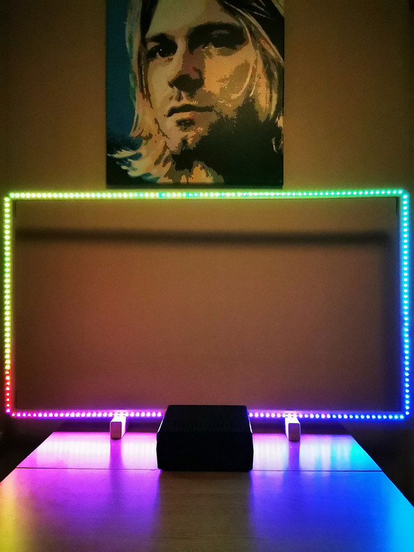
There is no one magic algorithm for RGB to RGBW conversion that works perfectly with every LED strip on the market. When I ran the first tests after building this setup the quality of the ambilight effect was poor and worse compare to the WS2801. That's because of the most common algorithm doesn't care at all about the white channel characteristics of the LED strip. In my case the light was a way too bright, warm and weak saturated. But I double check the order and I've ordered and received natural white version. Not the warm one. The solution was to calibrate RGB to RGBW conversion and it's done in https://github.com/awawa-dev/HyperSerialEsp8266 You can calibrate it also for your needs. After that I received beautiful colors: very natural and bright when is needed to but they don't lose a saturation what was a main problem before. Much better than WS2801.
Unfortunately you can't calibrate RGB to RGBW conversion in the HyperHDR "Image processing" tab because it's completely different process and it doesn't touch the white channel directly. You can use HyperSerialEsp8266 with individual setting per channel and WLED as it has build-in few preset mode also.
How to put all the things (hardware) together?
1) Parts
2) Frame or TV
3) Voltage level shifter
4) Measurement and testing
5) Soldering
6) Final result
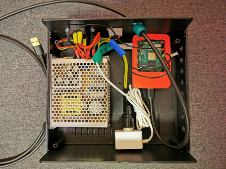
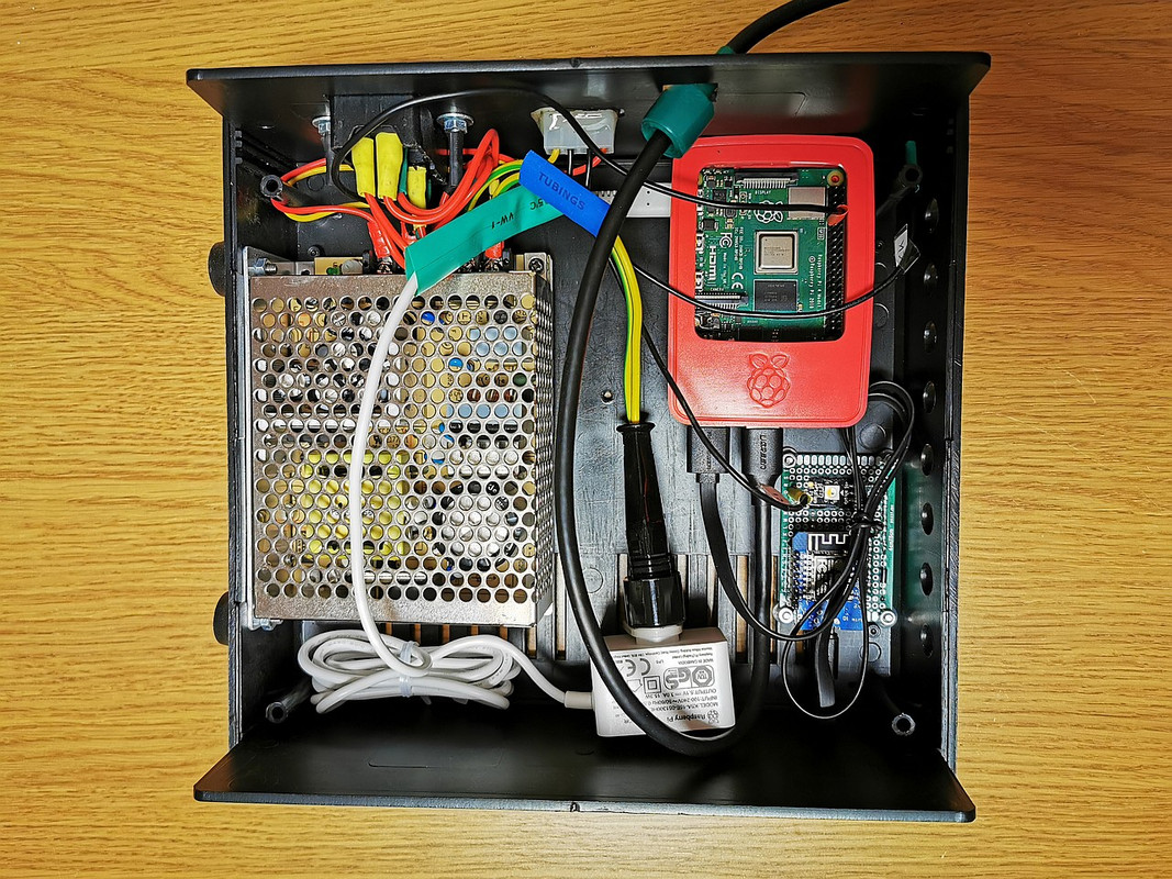
From previous setup I have: a plastic case with a switch with a fuse and molex connector for the LED strip on the back, modular power supply (Mean Well RS-75-5), Rpi 4 with dedicated power supply.
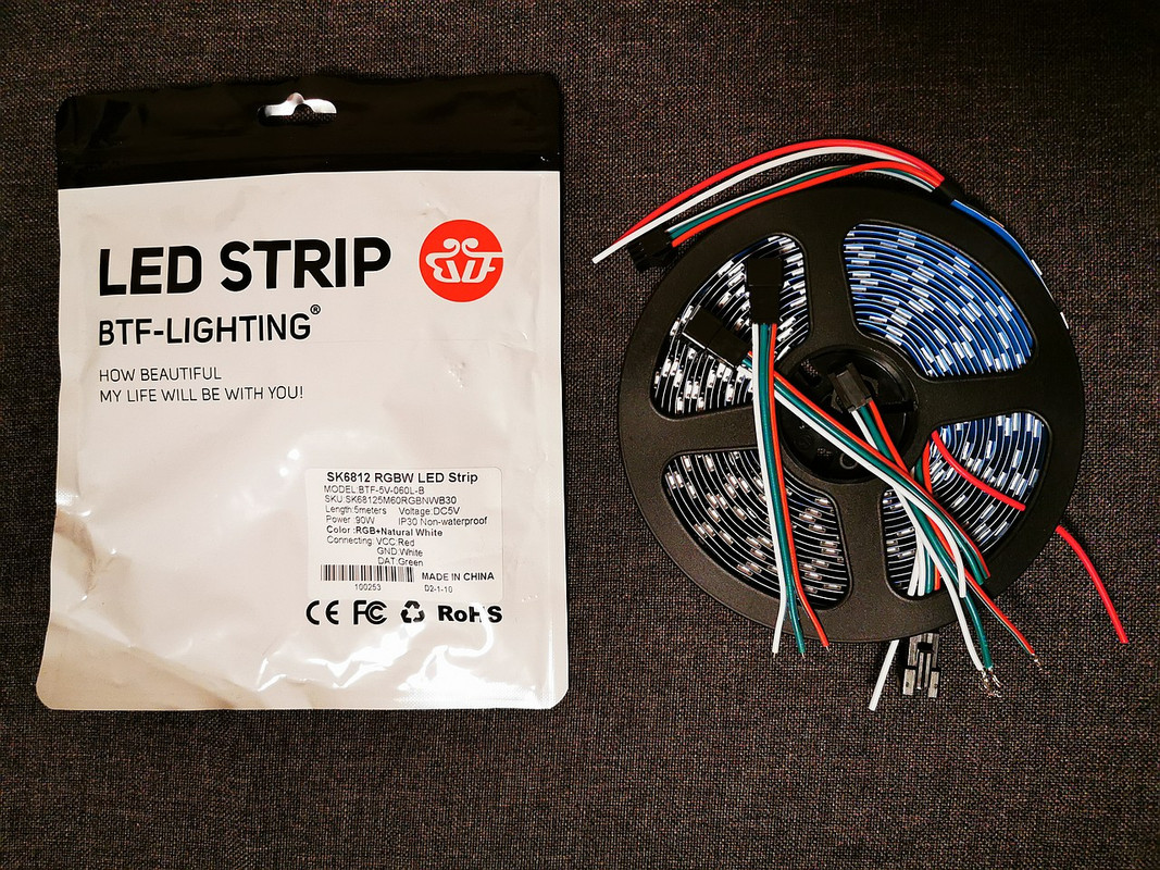
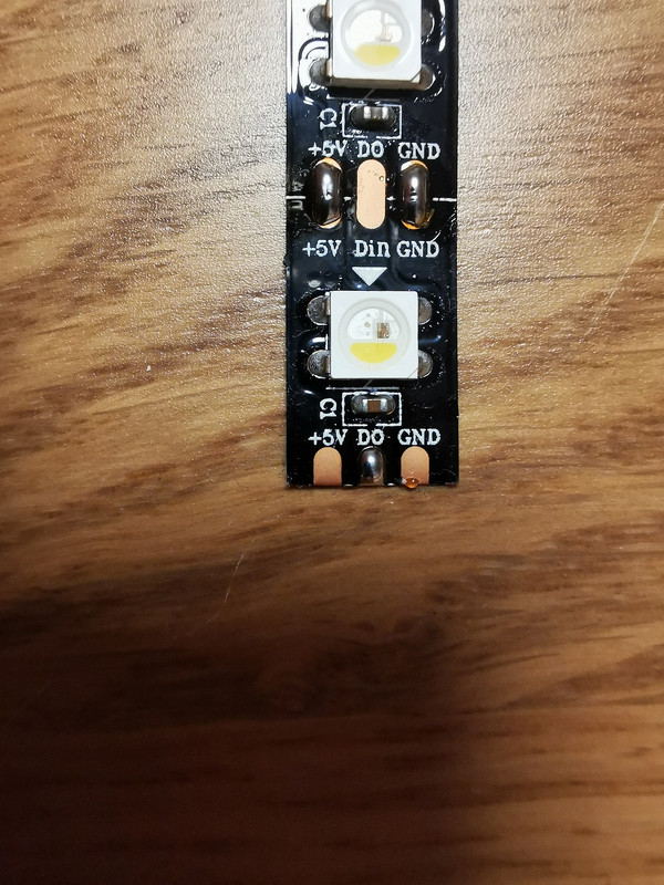
I will use now SK6812 RGBW 60 leds/meter from BTF-Lighting and wooden frame to mount it. I expected better quality and package protection from BTF but in the end it's acceptable.
My TV's back surface isn't flat. It's a problem to create even Ambilight effects on the wall and to attach the LEDs strip to the TV. Second problem is very long TV's stand that it keeps TV far from the wall. So I choose to use the wooden frame.
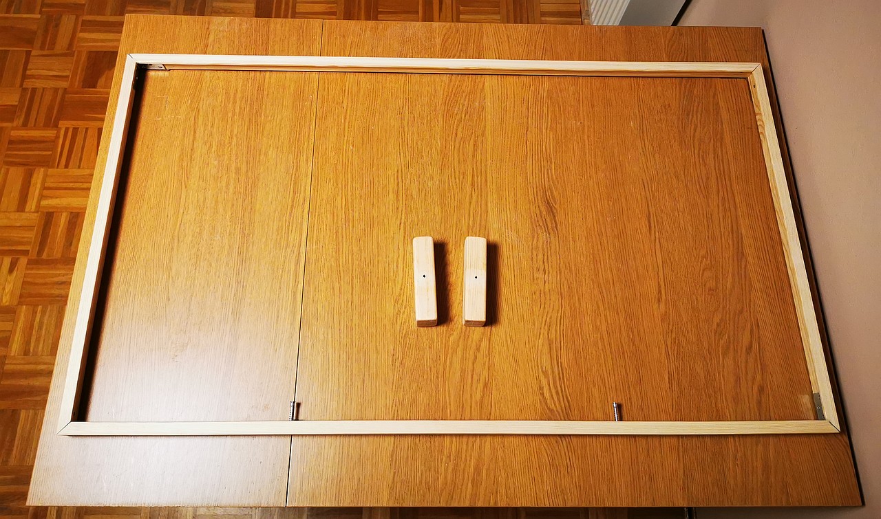
The dimension for my 55" LG is 122x68,5cm. The base's stands has 5cm height.
In my previous project (WS2801) I didn't use 3.3V to 5V level shifter and it worked. There were some random and very rare flashes, for example one per hour... sometimes it was OK for many hours/days, not sure if that was the problem. But now I don't want to take a risk. You can chose one of many available on the market IC level shifters but it must be a fast one. I found some opposite opinions (may not work well on higher bandwidth) about them and couldn't make a decision.
Then I found one old article about using one or two LED to increase 3.3V to level acceptable by the WS2812b/SK6812 controller. Link: https://www.electrobob.com/ws2812-level-translator/
In short: the LED feed by VCC = 5V requests al least 5V * 0.7 = 3.5V for data line . That's too high for 3.3V from Rpi/ESP8266, however it works in most case. But if we would feed first LED with just VCC = 4.3V then 3.3V would be perfectly fine for 4.3V * 0.7 = 3V. As a bonus the data signal after that passage would be amplified to VCC that was used (4.3V) and it would work then with the rest of the LED strip at VCC = 5V.
The problem could be the first LED but I take care of it in HyperSerialEsp8266 (WLED also has an option to skip it).
Here my implementation for Esp8266 Wemos d1 mini:


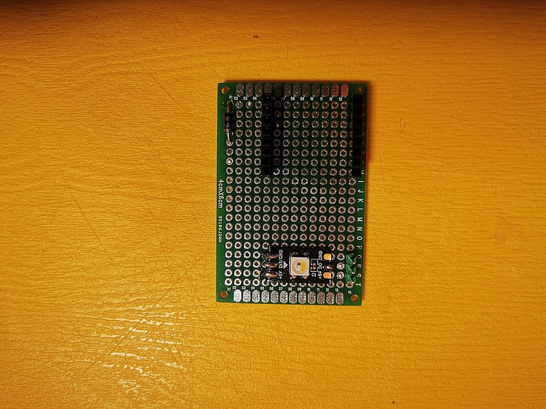
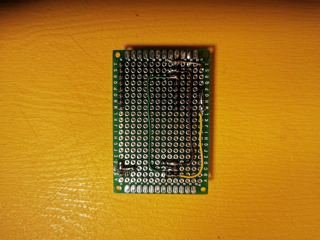
Used parts:
- ESP8266 with CH340G Wemos d1 mini clone and HyperSerialWLED or HyperSerialEsp8266 firmware
- prototype board
- some jumpers and wires
- one SK6812 LED
- 1N400x diode
The solution for WS2812B is almost the same: just use the same type of LED from the strip.
As all my components have common ground I need only that Data-Out from this level shifter.
Voilà
At this point you have working level shifter and WLED preferable to make some testing. Repairing the LED strip when it's already attached to the TV probable could be a very frustrating and difficult task. So we want to make sure it's working.
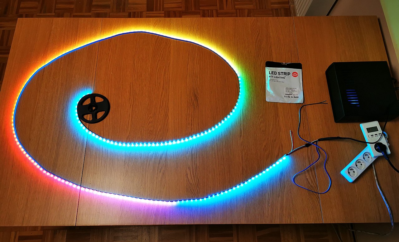
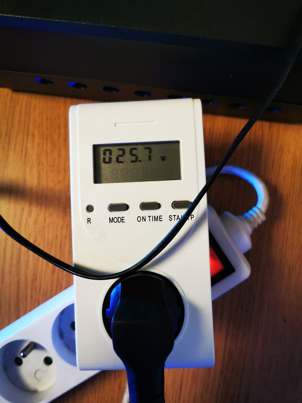
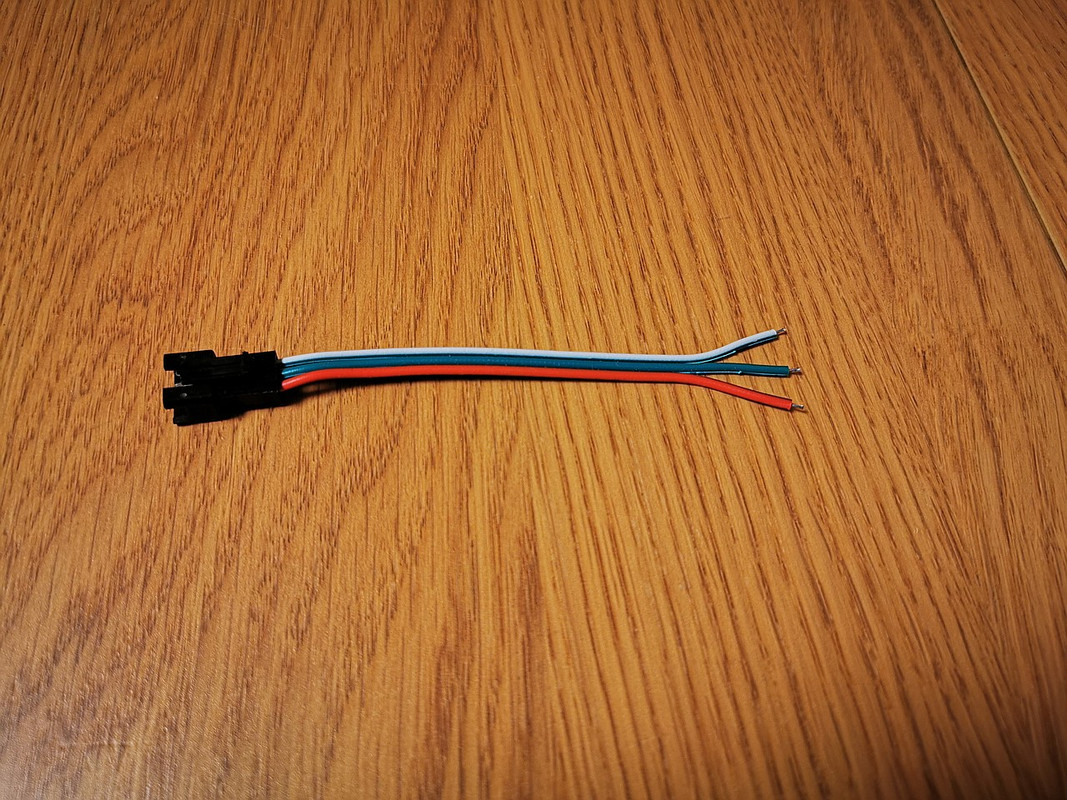
In my case everything was almost OK. LED strip was working, but I noticed one problem: the LED connector became hot when the LED strip was displaying white color for few minutes. And I tested only 3.5meter cut off segment of the LED strip. What would happen if I use full 5M LED strip? Probably it would become even hotter... The reason is poor quality of the wires used in this plug connector from BTF Lightning. I decided not to use it and to solder my proven cables directly to both ends of the LED strip at 5V and ground input (the data line is connected only at the beginning once of course). At the second end of this connector cable I have molex so I can disconnect the unit from the strip if I want to.
Despite I had already measured all the needed segments there was some drawback: one cut line laid almost directly on the soldering point from the BTF (the LED strip is constructed from connected 0.5m segments) and I had to cut it off, replace it and to solder new longer segment.
5) Soldering
Not a very pleasant process. Before I attached the segments to the frame I already prepared the soldering points with a tin:
I wanted to have very narrow corners. For data signal I used thin solid copper wire protected with liquid rosin against oxidization. But for +5V and ground you need a thick cables. I used too thick ones and it was difficult to solder them to the LED strip.
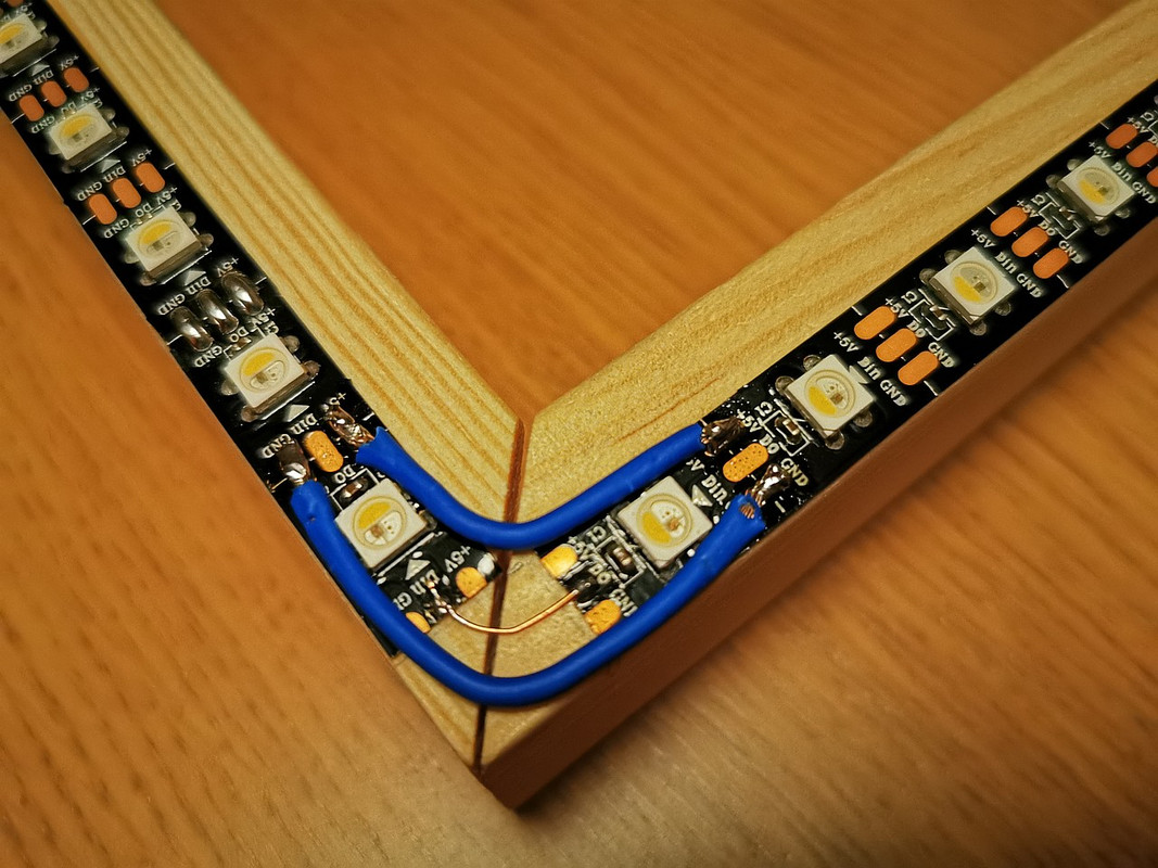
Not great, not terrible, but it's working. After every finished & soldered corner check with multi-meter the connectivity and also make sure that there's no short-circuits.

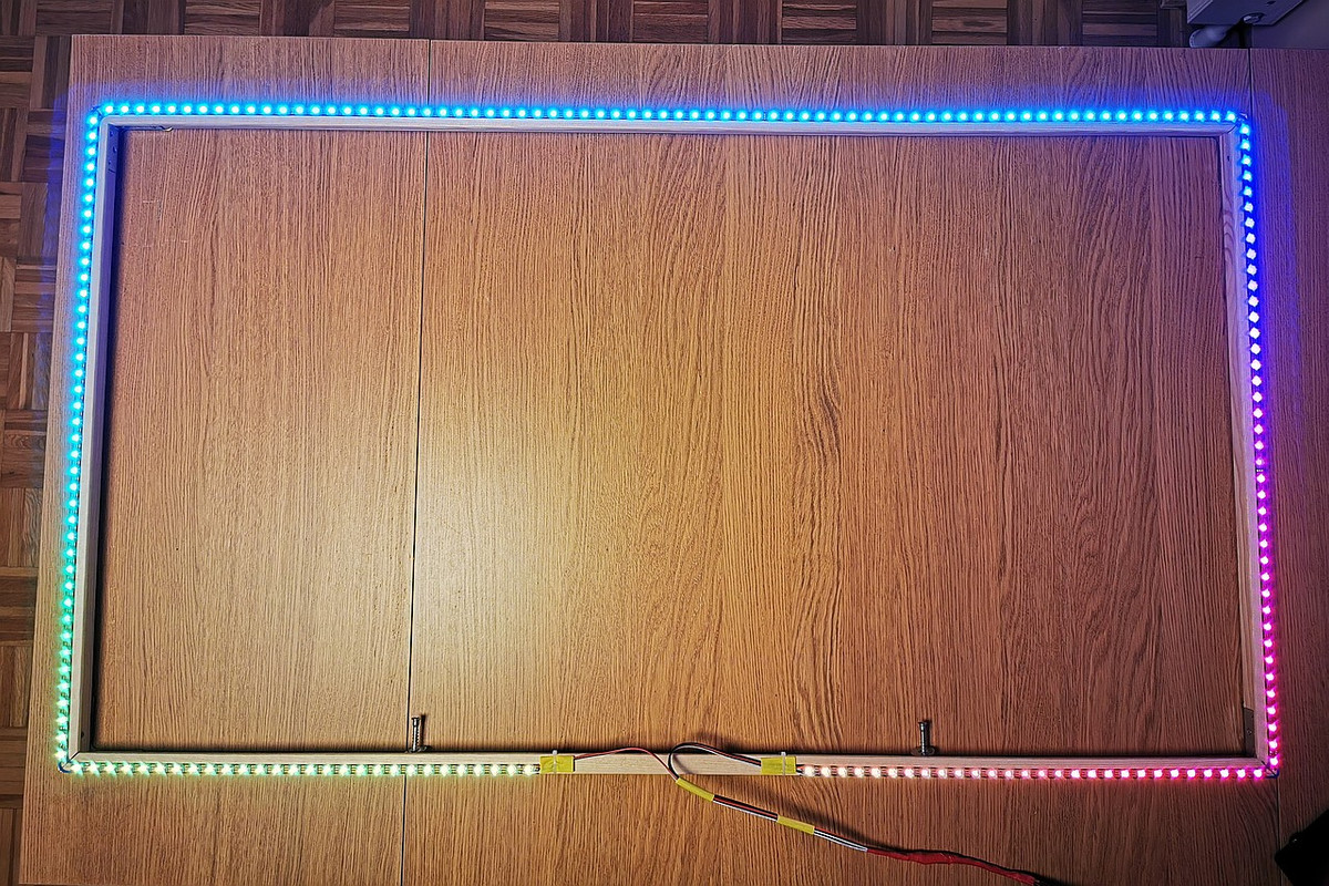
...it works! :)
It's time to attach the stands and to end the build.
Comments
- common ground for the RPI and ESP, if the ESP is connected to RPI by USB then also it shares the ground and it's enough: Raspberry Pi 4 PIN9 (not GPIO!) to the led strip power supply -V
- data line from ESP to the led used in the level shifter: it's GPIO2 on ESP, you must check schematic for you esp8266 which pin it is. In my case it's D4.
And remember that you serial chip esp8266 should support 2Mb serial transmission. Most popular are CH340g and cp2104. Avoid cp2102.
https://a.aliexpress.com/_u6DKj9
If everything works, I am going to buy an Ezcap 269. Thank you for your help.
I'm not using ezcap 269 anymore so can't verify it for sure, but from what I remember from users feedback, the grabber can pass Dolby Vision when it not exceeds 18 Gbps bandwidth but can't grab it (the image is pink).
As for the sound I use ezcap 269 for a quite long time and never experience a problem when it was connected to Denon x2700 even with high quality soundtracks. But again can't verify these particular systems now.
I'll be looking forward to the next EZcap review.
https://i.postimg.cc/3NqTsyP1/sound.jpg
If nothing happens in the video preview and there is a message about "grabber captured silence" in the log that means you grabber doesn't receive a sound. Some devices are very unfriendly and blocking forwarding sound stream for example Denon amplifiers.
So the grabber is not a problem if you set everything correctly and the grabber is RECEIVING sound.
1 setup your grabber for the sound effects in the: 'Effects' tab.
2 play a music your the device that is connected to the input of ezcap269, in hyperhdr run the equalizer 'Remote' tab, see the effect in the video preview as you had in the screenshot from my previuos post.
3 verify your logs if it is not working: without them we can only speculate.
At the end of the article.
Without a common ground in your setup you may experience not only problems with the communication...in fact it's a bit dangerous not to have it.
Also: whats the easiest way to level shift the signal?
My plan is to just have the WLED module hanging behind the tv. I want to power it from the TV's usb port if thats possible without sacrifizing anything? I mean the USB port should provide enough power for the ESP, correct?
I then want to have 2 long cables (ground and power) going to my lowboard under the tv. That way I would only have the small ESP behind the tv. How can I level shift with this set up?
Also which grabber is the absolute best you recommend right now? I consider getting the rullz one. The 2.0 is the good one, right? Or should I get the 3.0?
I want good hdr colors - I will use hyperhdr of course.
I know - many questions :D
I hope you can help me!
Thanks for the great work!
Also: whats the easiest way to level shift the signal? Do I need to level shift for my use case? I plan on only connecting the data pin to the ESP.
My plan is to just have the WLED module hanging behind the tv. I want to power it from the TV's usb port if thats possible without sacrifizing anything? I mean the USB port should provide enough power for the ESP, correct?
I then want to have 2 long cables (ground and power) going to my lowboard under the tv. That way I would only have the small ESP behind the tv. How can I level shift with this set up?
Also which grabber is the absolute best you recommend right now? I will get a good feintech hdmi matrix which has 2 outputs. 1 in 4k for the tv and 1 in fhd for the grabber. Will use it with an amazon fire tv stick mainly. I consider getting the rullz one. The 2.0 is the good one, right? Or should I get the 3.0?
Any ezcap is no upgrade for my use case right? And also more expensive..
I want good hdr colors - I will use hyperhdr of course.
I know - many questions :D
I hope you can help me!
Thanks for the great work!
2) CP2102 is limited only to 1Mb USB serial port speed so it is not compatible with HyperSerialEsp8266/HyperSerialESP32 if you experience problems with the Wifi signal stability and want to switch for the cable solution.
3) ESP module with enabled Wifi can draw up to 800ma from the USB port. USB2.0 standard limit is 500ma so it depends on your TV USB port implementation.
4) Voltage level shifting is for data line, not ground and power. But watch out for the voltage drop if there are really long, use thick cables. +5V for a level shifter should be taken from that power cable just before the LED strip (not for example from +5V ESP module because they could be different due to the voltage drop).
5) For all in one solution: Ezcap 320, for HDMI splitter + grabber: Ezcap 321 (really fast and true USB3.0) or budget solution MS2109 (there are different implementation...if it's true USB3.0 and still can offer YUV then it could be a better choice, anyway it's a lottery. USB2.0 version from proven seller/brand is also good choice).
First of all, the existing system doesn't have a lot of latency, but your system doesn't seem to have any latency.
First of all, this is a video of my system in operation. The latency is about the same as watching a video.
https://youtu.be/pHli40kIyy8
would you have any wiring diagram how do I connect all the stuff?
I understand that signal from the grabber goes into HyperHDR holding device (in my case it is RPi 0), then I use default pin (GPIO18) for controlling LEDs. I want to include HyperSerialEsp8266 with level shifter, how do I connect RPi with Esp8266? Signal from Esp8266 goes using GPIO2 into level shifter and then into LEDs, right? But I am missing link between RPi and Esp8266...
Regards,
Maciek
You have two ways to connect Rpi to Esp8266:
- just USB connection, but ESP8266 must have CH340C, CH340G, CP2104 serial chip on board supporting 2Mb speed. This can be difficult since the ch340x family is more often counterfeited with some unnamed ones that usually don't work at 2Mb speed (their chip's tags are phisically removed from the surface). For more details, see HyperSerialEsp8266 or here HyperSerialWLED
- using SPI connection between Rpi and any generic ESP8266. Our colleague @bong8839 did a good job of creating a schematic for him which can be found here: I want to change Hyperion to HyperHDR. # 182 HyperSPI project is located here: HyperSPI
Post a Comment